What is a pure inductive circuit and a pure resistance circuit?
Pure inductance circuit and pure resistance circuit are two basic circuit models, which respectively represent the ideal case of only inductance or only resistance components in the circuit. The following describes the two circuit models and their characteristics:
Pure Resistor Circuit
Definition
A pure resistance circuit is a circuit that contains only resistance components (R) and no other types of components (such as inductors L or capacitors C). Resistance elements are used to represent the part of the circuit where energy is dissipated, such as the generation of heat.
Peculiarity
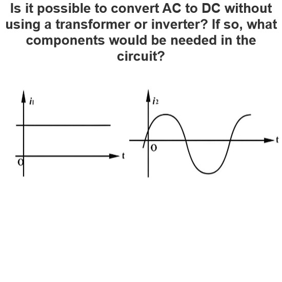
Voltage and current in phase: In a pure resistance circuit, the voltage and current are in phase, that is, the phase difference between them is 0°.
Ohm's Law: The relationship between voltage (V) and current (I) follows Ohm's law, i.e., V=I×R, where R is the resistance of a resistor.
Power consumption: The resistive element consumes electrical energy and converts it into heat energy, calculated by power P=V×I or P= V2/R or P=I 2×R.
Apply
Heating element: Resistance element is very common in heating equipment, such as electric water heater, electric iron, etc.
Current limiting element: Used as a current limiting element in a circuit to prevent excessive current from damaging other components.
Voltage divider: In a voltage divider circuit, a resistor is used to distribute voltage proportionally.
Pure Inductor Circuit
Definition
A pure inductive circuit is a circuit that contains only inductive elements (L) and no other types of components. An inductor represents the part of a circuit that stores magnetic field energy and is usually composed of wound coils.
Peculiarity
Voltage lead current 90° : In a pure inductive circuit, the voltage is 90° ahead of the current (or +90° phase difference).
Inductive reactance: The inductive element's blocking effect on alternating current is called inductive reactance (XL), and its size is proportional to the frequency, the calculation formula is
XL=2πfL, where f is the frequency of the alternating current and L is the inductance value of the inductor.
Reactive power: Inductive elements do not consume energy, but will store energy in the magnetic field and release it in the next cycle, so there is reactive power (Q) in the inductive circuit, but no actual energy consumption.
Apply
Filters: Inductors are often used in filters, especially low-pass filters, to block the passage of high-frequency signals.
Ballast: In fluorescent lamp circuits, inductors are used as ballast, limiting current and providing the necessary starting voltage.
Resonant circuit: When used with capacitive components, inductors can form LC oscillating circuits for generating oscillating signals of a specific frequency.
Sum up
Pure resistance circuit: characterized by voltage and current in phase, following Ohm's law, energy consumed on the resistance, converted into heat.
Pure inductive circuit: characterized by voltage leading current 90°, inductive reactance, energy stored in the magnetic field and released in the next cycle, no energy consumption.
In practical applications, pure resistance or inductance circuits are rarely encountered, and often a combination of multiple components is included in the circuit, but understanding these two basic circuit models helps to analyze and design more complex circuits.
The Electricity Encyclopedia is dedicated to accelerating the dissemination and application of electricity knowledge and adding impetus to the development and innovation of the electricity industry.


