Electrical Polarity: What is it?
Now consider an AC circuit with two voltage sources. Here, magnitude, polarity, and phase angle are used to find the equivalent voltage.
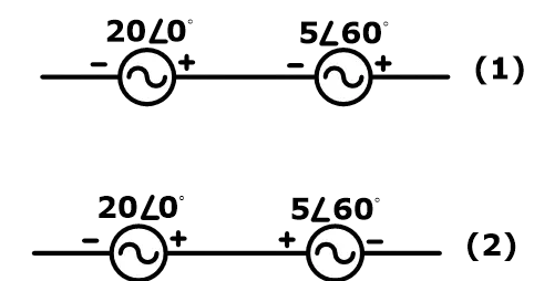
In the first figure, both sources have the same polarity. Hence, the equivalent voltage is the addition of both. But these are the polar form—
First, we need to convert this polar form into a rectangular form. And it will be—
Now, the equivalent voltage is the addition of each of the X-components and Y-components (i.e. ![]() )—
)—
Again, convert the rectangular form into polar form and we will get—
In the second figure, both sources have opposite polarities. In this case, the equivalent voltage is a subtraction of both voltages—
Now, we can add both ![]() and
and ![]() to find an equivalent voltage—
to find an equivalent voltage—
Conventions for Identification
According to the polarity, we can find the direction of the current flowing through the active and passive components.
In the passive element, ohm’s law gives a relation between voltage and current. But the voltage polarity and current direction are necessary to assign.
Voltage polarity and current direction depend on each other. The convention identification of voltage polarity and current direction in passive elements is shown in the figure below.
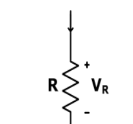
So, according to convention law, the current flows from positive polarity to negative polarity. But in actuality, the current flows from negative polarity to positive polarity.
In conventional identification, we assumed the current flows due to proton (positive charge). But according to the actual definition of current, it is the flow of electrons (negative charge).
And there is no difference if we consider the conventional or actual direction.
What is Electrical Polarity?
Electrical polarity is used to define the state of a body or system with respect to other bodies or systems. It is a relative quantity.
Electrical polarity is classified into two types—
Positive polarity
Negative polarity
The polarity of a body or system that has a greater number of electrons is considered the negative polarity. And the polarity of the remaining body or system is considered the positive polarity.
The polarity plays an impotent role in connecting polarity-dependent devices like measuring meters, electrical machines, batteries, etc.
The electrical polarity is also used to determine the flow of current. Polarity is also referred to in terms of “terminals”, i.e. as the positive and negative terminals.
In sources, the current flows from the positive to the negative terminal and in circuit elements (like resistors), the current flows from the negative to the positive terminal.
In a DC circuit, the current flows in one direction.
AC Polarity
The direct current flows in one direction only. It is a constant current. But an alternating current (AC) changes its polarity from every half cycle.
For 50Hz current, the waveform changes its polarity at each 10ms. And the polarity changes 100 times in one second.
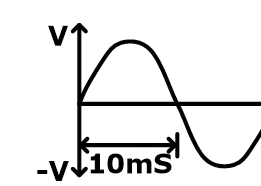
In a DC system, the magnitude and polarity are sufficient to describe. But, in an AC system, an angle (time-shift between two signals) must be considered with magnitude and polarity.
The voltage is never signed negative (-) in the AC system. The polarity of the source will decide to either add or subtract.
How Does Electrical Polarity Work?
The electrical polarity gives information about the direction of current through the circuit. The polarity depends on the number of electrons.
It is said to be negative polarity if the number of electrons is more. And other is assigned as positive polarity.
The electrical polarity decides the direction of the flow of current. Also, it is very important if more than one voltage source is connected to the circuit.
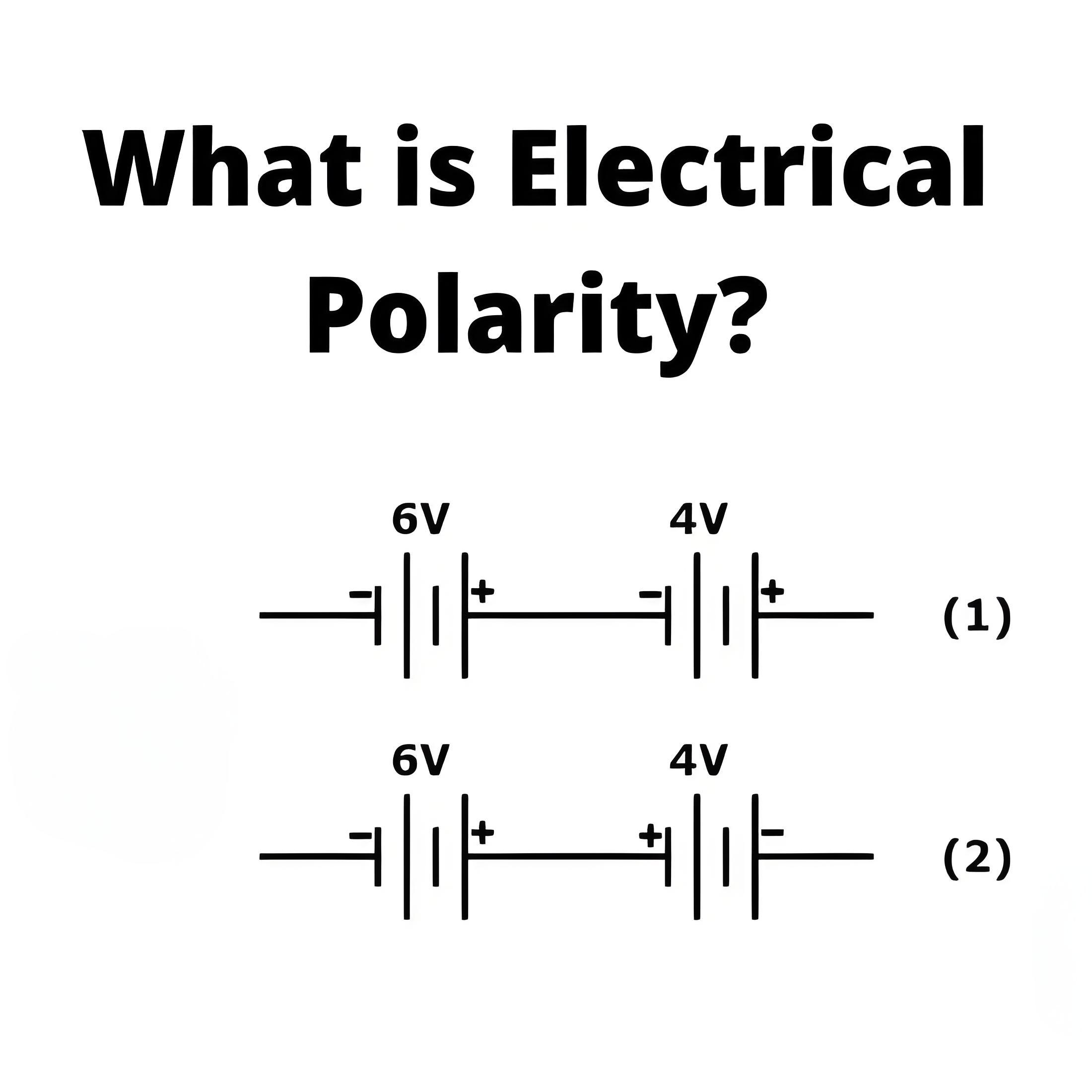
Consider a DC circuit with two sources. If both sources have the same polarity, the total available voltage is added. And if both sources have opposite polarity, the total available voltage is subtracted.
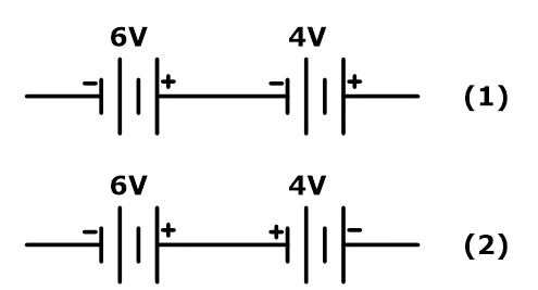
In the first figure, both sources have the same polarity. Hence, the total voltage available to the circuit is 10V.In the second figure, the polarity of both sources is opposite. Hence, the total voltage available is 2V.
Source: Electrical4u
Statement: Respect the original, good articles worth sharing, if there is infringement please contact delete.
Electrical4U is dedicated to the teaching and sharing of all things related to electrical and electronics engineering.

