Transformer Winding Resistance Testing
Winding Resistance Test Definition
The winding resistance test of a transformer checks the health of transformer windings and connections by measuring resistance.
Procedure of Transformer Winding Resistance Measurement
For star connected winding, the resistance shall be measured between the line and neutral terminal.
For star connected autotransformers the resistance of the HV side is measured between HV terminal and IV terminal, then between IV terminal and the neutral.
For delta connected windings, measurement of winding resistance shall be done between pairs of line terminals. As in delta connection the resistance of individual winding can not be measured separately, the resistance per winding shall be calculated as per the following formula:
Resistance per winding = 1.5 × Measured value
The resistance is measured at ambient temperature and converted to resistance at 75°C for comparison with design values, past results, and diagnostics.
Winding Resistance at standard temperature of 75oC

Rt = Winding resistance at temperature t
t = Winding temperature
Generally, transformer windings are immersed in insulation liquid and covered with paper insulation, hence it is impossible to measure the actual winding temperature in a de-energizing transformer at the time of transformer winding resistance measurement. An approximation is developed to calculate the temperature of winding at that condition, as follows
Temperature of winding = Average temperature of insulating oil
The average temperature of insulating oil should be taken 3 to 8 hours after de-energizing transformer and when the difference between top and bottom oil temperatures becomes less than 5oC.
The resistance can be measured by a simple voltmeter ammeter method, Kelvin Bridge meter or automatic winding resistance measurement kit (ohm meter, preferably 25 Amps kit).
Caution for voltmeter ammeter method: Current shall not exceed 15% of the rated current of the winding. Large values may cause inaccuracy by heating the winding and thereby changing its temperature and resistance.
Note: The measurement of winding resistance of a transformer shall be carried out at each tap.
Current Voltage Method of Measurement of Winding Resistance
The transformer winding resistances can be measured by current voltage method. In this method of measurement of winding resistance, the test current is injected to the winding and corresponding voltage drop across the winding is measured. By applying simple Ohm’s law i.e. Rx = V ⁄ I, one can easily determine the value of resistance.
Procedure of Current Voltage Method of Measurement of Winding Resistance
Before measurement, the transformer should be off and without excitation for 3 to 4 hours. This allows the winding temperature to match the oil temperature.
Measurement is done with D.C.
To minimize observation errors, polarity of the core magnetization shall be kept constant during all resistance readings.
Voltmeter leads shall be independent of the current leads to protect it from high voltages which may occur during switching on and off the current circuit
The readings shall be taken after the current and voltage have reached steady state values. In some cases this may take several minutes depending upon the winding impedance.
The test current shall not exceed 15% of the rated current of the winding. Large values may cause inaccuracy by heating the winding and thereby changing its resistance.
For expressing resistance, the corresponding temperature of the winding at the time of measurement must be mentioned along with resistance value. As we said earlier that after remaining in switch off condition for 3 to 4 hours, the winding temperature would become equal to oil temperature. The oil temperature at the time of testing is taken as the average of top oil and bottom oil temperatures of transformer.
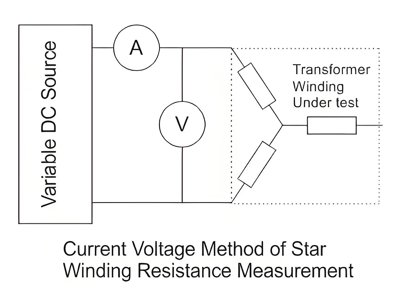
For star connected three-phase winding, the resistance per phase would be half of the measured resistance between two line terminals of the transformer
For delta connected three-phase winding, the resistance per phase would be 0.67 times of measured resistance between two line terminals of the transformer.
This current voltage method of measurement of winding resistance of transformer should be repeated for each pair of line terminals of winding at every tap position.
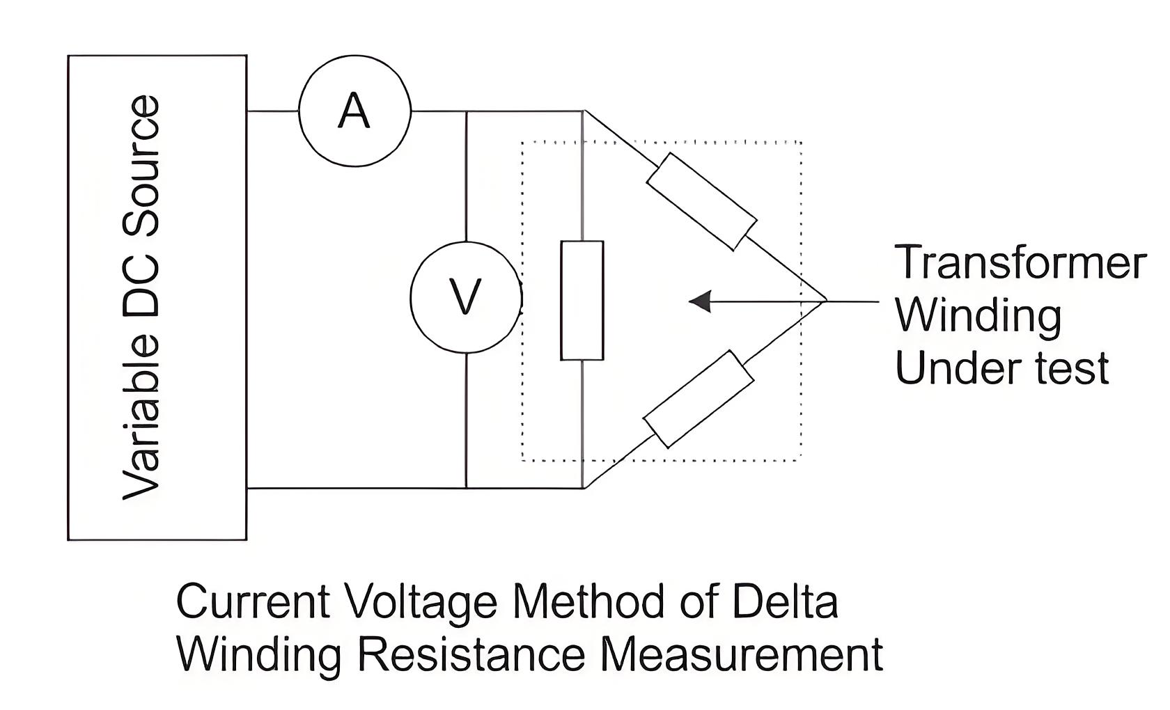
Bridge Method of Measurement of Winding Resistance
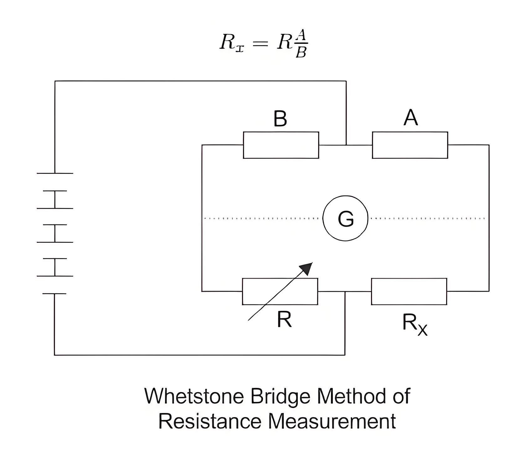
The main principle of the bridge method is based on comparing an unknown resistance with a known resistance. When currents flowing through the arms of the bridge circuit become balanced, the reading of galvanometer shows zero deflection that means at balanced condition no current will flow through the galvanometer.
A very small value of resistance (in milli-ohms range) can be accurately measured by the Kelvin bridge method whereas for higher value Wheatstone bridge method of resistance measurement is applied. In bridge method of measurement of winding resistance, the errors are minimized.
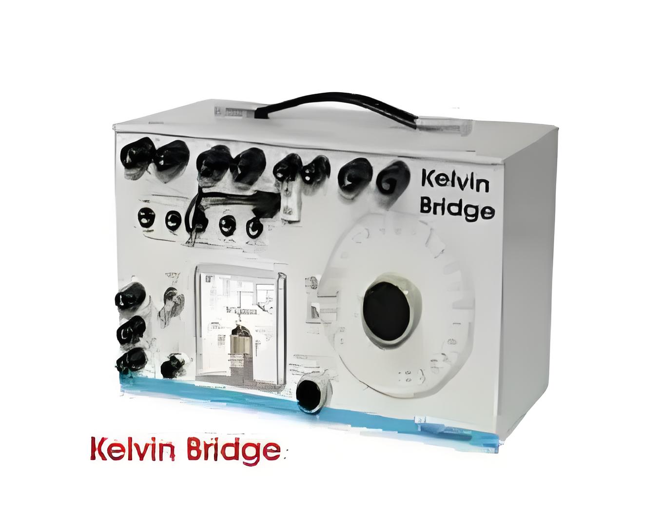
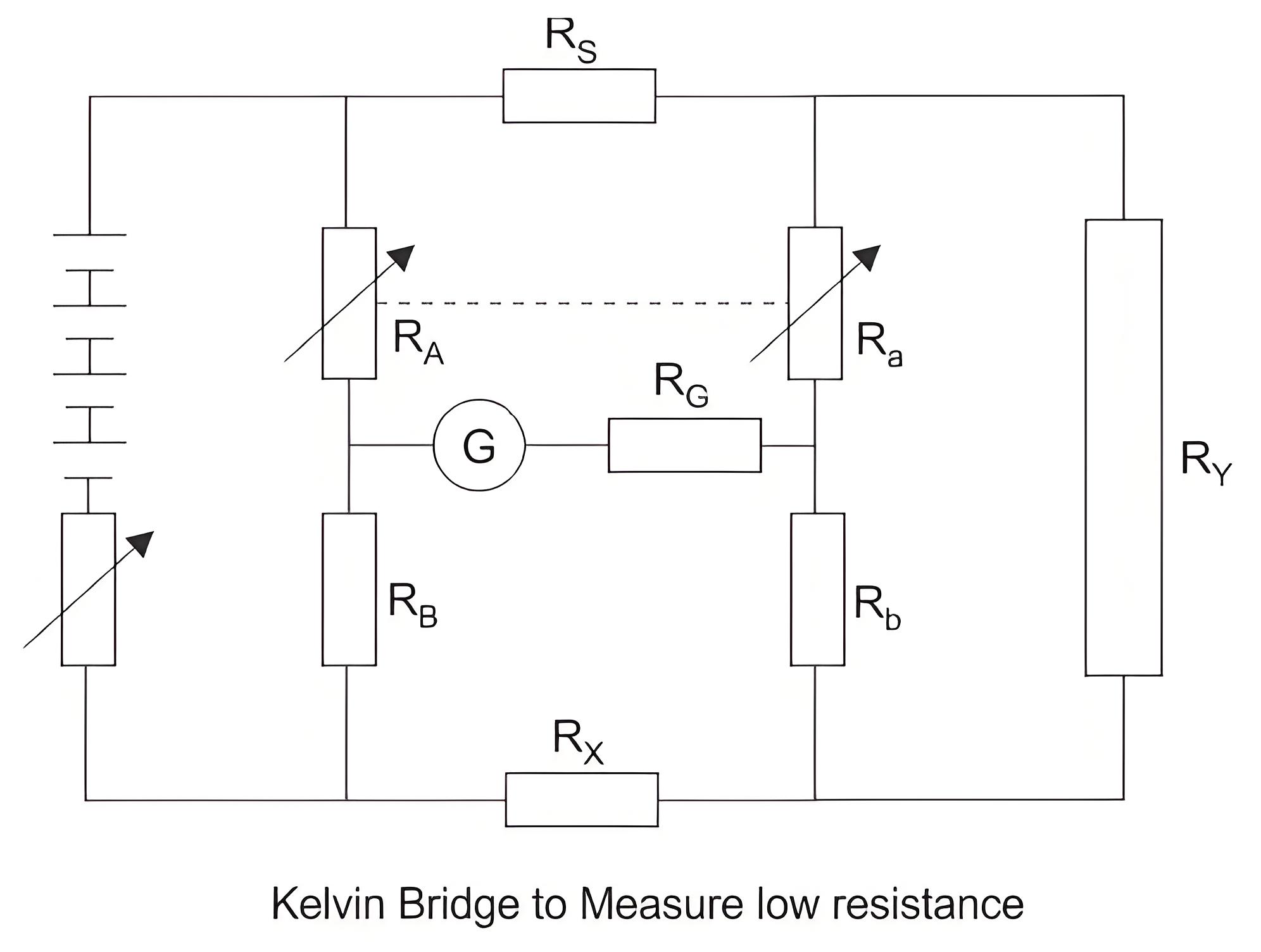
The resistance measured by Kelvin bridge
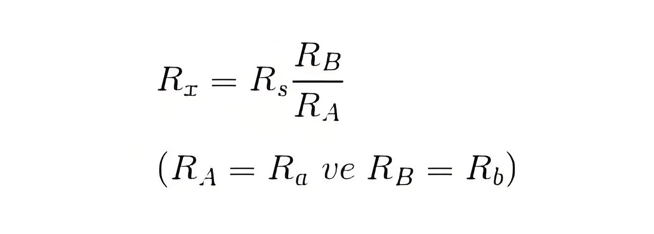
All other steps to be taken during transformer winding resistance measurement in these methods are similar to that of current voltage method of measurement of winding resistance of transformer, except the measuring technique of resistance.
The resistance measured by Wheatstone bridge,
Welcome to our electricity community! Established to facilitate the exchange and cooperation in the electricity industry and bridge professionals, enthusiasts, and related enterprises.


