What is a Voltage Sensor?

A sensor is an electrical device that detects and responds to a certain sort of signal, such as optical or electrical. The use of sensor methods in voltage (or) current measurement has become an excellent alternative for voltage and current measurement methods. Sensors provide many benefits over traditional techniques of measurement, including reduced size & weight, high safety, high precision, non-saturability, eco-friendliness, and so on. It is possible to combine current and voltage monitoring into a single physical device with small and solid dimensions. This post gives a brief description of the voltage sensor & how it works.

What is a Voltage Sensor?
This sensor measures, calculates, and determines the voltage supply. This sensor can detect the amount of AC or DC voltage. This sensor’s input may be voltage, and its output can be
Switches,
Analogue voltage signals,
Current signals,
Audio signals, and so on.
Some sensors produce sine waveforms or pulse waveforms, while others may produce
AM (Amplitude Modulation),
PWM (Pulse Width Modulation), or
FM waveforms (Frequency Modulation).
The voltage divider may affect the measurement of these sensors.
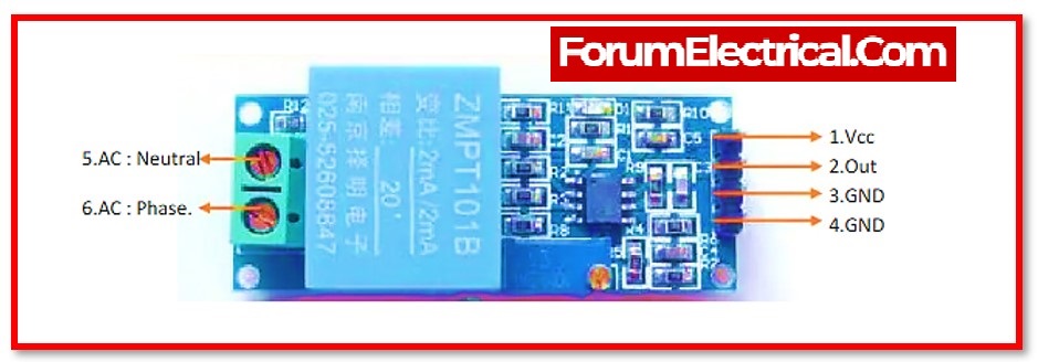
This sensor has both input and output. The input side consists mostly of two pins, positive and negative. The device’s two pins may be linked to the sensor’s positive and negative pins. The device’s positive and negative pins may be linked to the sensor’s positive and negative pins. This sensor’s output primarily contains
Supply voltage (Vcc),
Ground (GND), and
Analogue o/p data.
Function of a Voltage Sensor
Voltage sensors are capable of detecting a wide range of phenomena, including the following:
1). Magnetic Fields
2). Electromagnetic Fields
3). Contact Voltage
1). Magnetic Fields
2). Electromagnetic Fields
3). Contact Voltage
Sensors that are primarily designed to monitor contact voltage have a broad range of potential applications and sectors in which they might be used. Battery monitoring is a typical example of an application. One piece of equipment may have a battery placed in it, but some months later, the battery may get dislodged and fall out of its proper location. This sensor will be able to identify that there has been a decrease in the contact voltage and will notify the CMMS of the change. The next step is for a maintenance professional to follow up and re-establish contact with the user.
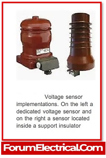
Voltage Sensor Types
These sensors are divided into two types:
Resistive voltage sensors and
Capacitive voltage sensors.
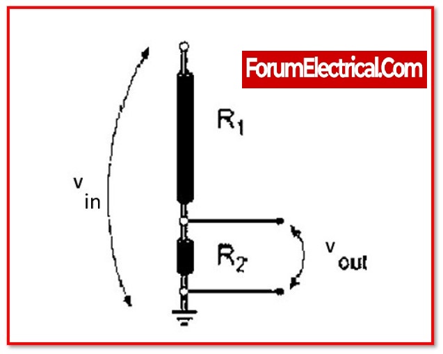
1). Resistive Voltage Sensors
This sensor primarily consists of two circuits:
a voltage divider and
a bridge circuit.
In the circuit, the resistor serves as a sensing element. To create a voltage divider circuit, split the voltage into two resistors, such as
a reference voltage and
a variable resistor.
This circuit is powered by a voltage source. The resistance in the circuit determines the output voltage. As a result, the voltage change might be increased.

Four resistors may be used to construct the bridge circuit. Any of these resistors may be tested using the voltage detector.
The voltage difference may be seen immediately. This difference alone may be amplified however the difference inside the voltage divider circuit not simply amplified.
Vout = (R1/R1 + R2) x Vin
Where,
R1,R2 – Resistors
Vin – Input Voltage and
Vout – Output Voltage.
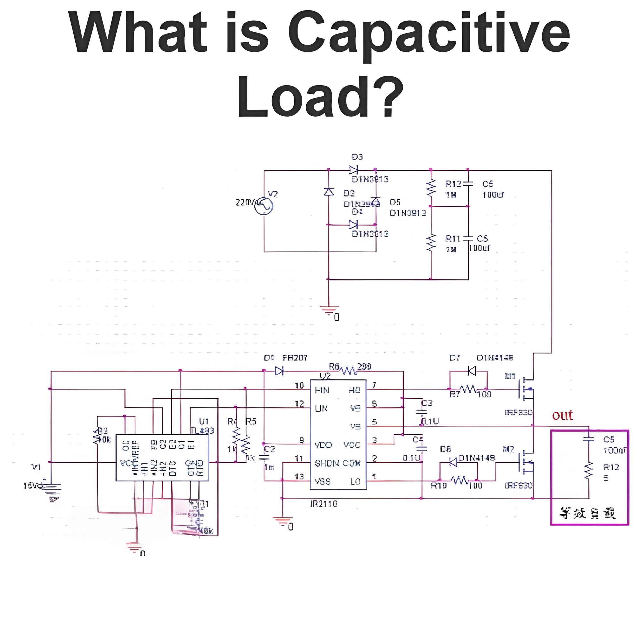
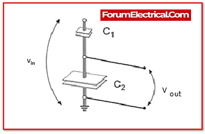
2). Capacitive Voltage Sensors
This sensor is composed of an insulator & two conductors in the center. Since the capacitor is powered by 5 volts, current will flow through it. This may cause current inside the capacitor to flow. The difference in capacitance shows the voltage, and the capacitor may be linked in series.
Vout = (C1/C1 + C2) x Vin
Where,
C1,C2 – Capacitors
Vin – Input Voltage and
Vout – Output Voltage.
And being aware that 2 conductor plates are employed in a capacitor. Between these two plates, the conductor is placed. This non-conductive substance is referred to as a dielectric. When an AC voltage is supplied to this plate, a current will flow owing to the attraction of the electron (or) interference from the voltage (V) across the opposite plate.

The space between these 2 plates will create a full AC circuit without the need for any additional gear. This is the operation of a capacitor.
Secondly, consider the voltage split between two series-connected capacitors. Typically, a high voltage will arise in a series circuit component with a high resistance. In the case of a capacitor, capacitance & impedance are always in proportions that are opposite to one another.
XC=1/2ΠfC
Where,
XC – Capacitive reactance denoted in Ω.
f – Frequency denoted in Hertz.
Voltage and capacitance have the following relationship:
V= Q/C
Where,
Q – Charge denoted in Coulomb.
C – Capacitance denoted in Farad.
According to the previously mentioned calculation, it is clear that the lowest voltages will merge in a smaller capacitor. This is the basic principle on which the capacitor voltage sensor operates. Imagine hold the sensor in our arm and position its edge (tip) next to the live conductor.
Here, a series of capacitive coupling circuits receive the sensory element of high impedance. At now, the sensor’s tip has the smallest capacitor coupled to a live voltage.
As a result, the whole voltage will grow into a sensing circuit. It detects voltage and activates a buzzer or light. This is the rear of the non-contact voltage sensor used in house.
Based on the power utility it is classified as,
AC Sensors,
DC Sensors and
Specialized Sensors.
3). AC Sensors

The AC voltage is measured using these sensors. The regulation of power consumption, the detection of power failures, and the sensing of loads are all examples of typical uses. AC sensors allow for not only the management of safety switching but also the control of motor overload.
4). DC Sensors
These sensors are need to monitor DC voltage. DC voltage sensors are useful for a variety of applications, including energy management & building control systems. In addition to these, other popular uses include data collecting, temperature management, and the detection of faults.
5). Specialised Sensors
Other different types of voltage sensors that are ideally equipped to certain applications are going to be created as technology develops further. For instance, applications that employ high voltage could need specialised sensors, and a lot of them make use of fibre optic components to monitor the voltage levels.
Basic PIN Configuration of Voltage Sensor
| Basic PIN Configuration of Voltage Sensor | Function |
|---|---|
| VCC | Pin on the positive power supply. This pin is linked to the positive terminal of the power source that is being evaluated, thus measure its output. |
| GND | Reference potential pin. It has a wire running from it directly to the power supply’s negative terminal. |
| S | Sensor analogue output pin voltage. Attach it to the microcontroller’s analogue input pin if intend to utilise it. |
| + | Not-Connected |
| – | pin used for grounding. It has to be connected to both the power supply ground pin and the ground pin of the microcontroller. |
Advantages of the Voltage Sensors
The atmosphere is conducive.
An abundance of dynamic range.
Non-satisfactory.
Improves worker safety.
Small in weight & size.
The level of accuracy is extremely great.
Disadvantages of the Voltage Sensors
It responds non-linear response.
It is characterised by hysteresis.
It has less sensibility.
It has a high-power use.
Applications of Voltage Sensors
Identifies the breakdown of electricity.
Load sensing.
Keeping the temperature under control.
Control of the power demand.
Fault finding.
Demand for power is kept under control.
Protective switching.
Below are some common applications for voltage sensors.
1). Power Demand Monitor
2). Power Failure Monitoring
3). Load Sensing
4). Fault Detection
5). Temperature Control
6). Safety Switching
7). Motor Overload Control
8). Energy Management Controls
9). Building Control Systems
10). Fault Detection
11). Data Acquisition
1). Power Demand Monitor
With the use of sensors, one can keep track of which types of property and machinery consume the most electricity. Then, decisions relating to the efficiency of energy use or the conservation of energy may be taken.
2). Power Failure Monitoring
It is obvious that a loss of electricity may have catastrophic implications on the establishments of a facility. A decline in voltage, which may indicate an approaching power outage, might trigger an alarm for management if voltage sensors are installed.
3). Load Sensing
It is usual feature to use these sensors in hydraulic systems so that one may determine whether or not a certain pump is operating appropriately.
4). Fault Detection
They are helpful in determining the specific location of a problem in a piece of machinery or in the larger system as a whole.
5). Temperature Control
Temperature sensors, which are meant to determine if an object or zone is within an acceptable temperature range, might collapse. If it occurs, the monitoring they provide is considered useless. When this happens, the devices often release an excessive amount of voltage, which a voltage sensor is able to pick up on.
6). Safety Switching
The possibility of receiving an electric shock is increased when there are faulty wires present. Voltage sensors may be wired up to a safety switching system, which will then automatically turn off the power supply or reroute it if it detects an unsafe condition. In addition, a warning may be sent so that the damaged wires can be fixed.
7). Motor Overload Control
Monitoring and detecting the current taken from an overworked motor is possible with the help of voltage sensors. When a certain point is reached, the engine is able to turn off in order to avoid causing any costly damage.
8). Energy Management Controls
These sensors may assist a facility optimise the production of energy, the transmission of that energy, and the utilisation of that energy inside a firm by giving data on the voltage usage.
9). Building Control Systems
In order for a company to run efficiently, the controls of the building, including things like the security and HVAC systems, need to be operational at all times. It is possible for these sensors to assist in ensuring that these systems are in proper functioning condition.

10). Fault Detection
It is possible that there has been a fault in the equipment if the voltage has dropped to an unsafe level or is approaching dangerously high levels. After then, tasks of preventive maintenance may be arranged in advance of the start of major problems.
11). Data Acquisition
They have the potential to make a substantial contribution towards the establishment of previous maintenance data in the CMMS. It will be able to make better options for the long term if gather data on the performance of equipment as well as the frequency of their maintenance.
Frequently asked Question:
1). What is meant by the term “voltage sensor circuit”?
A circuit that is capable of sensing the voltage that is fed into it is referred to as a voltage sensor circuit. When the voltage approaches a certain level, an indicator like an LED will light up to know it’s time to take action.
2). What are voltage sensor faults?
Three general categories are used to classify faults in voltage sensors and current sensors:
Scaling fault,
Stuck fault, and
Bias fault.
3). What does the term “current sensor” mean?
A device that can measure the amount of electrical current that is flowing across a circuit is known as a current sensor.
Conclusion
A voltage sensor can be used to determine the voltage range present in any equipment. It is responsible for determining the electrical charge that exists within every device. This sensor operates primarily according to either the capacitive or resistive principle.
Statement: Respect the original, good articles worth sharing, if there is infringement please contact delete.

Welcome to our electricity community! Established to facilitate the exchange and cooperation in the electricity industry and bridge professionals, enthusiasts, and related enterprises.

