Hybrid HVDC Breaker Definitions
Definitions for Hybrid HVDC Circuit Breakers
Standard Definitions for AC Circuit Breakers
- Limitations: The standard definitions for AC circuit breakers do not directly translate to HVDC protection because the time frames and dynamics involved are different.
- Time Frames: AC circuit breakers have a relatively long time to act compared to DC circuit breakers. Typically, the fault currents that an AC circuit breaker interrupts will have nearly reached steady state by the time the protection acts, but this is not always the case.

HVDC Circuit Breakers
- Response Time: HVDC circuit breakers must act before the DC fault current has reached a steady state value, due to the limitations of the electronics within the circuit breakers and the converters themselves.
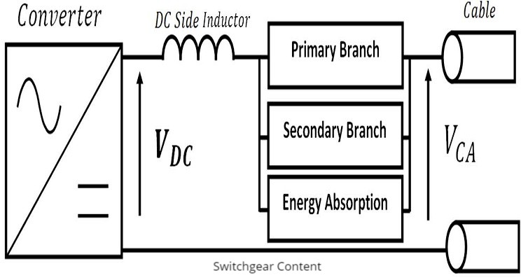
Key Branches and Their Functions
-
Primary Branch:
- Conducts the current during normal operation.
-
Secondary Branch:
- Conducts the fault current for a short period of time.
-
Energy Absorption Branch:
- Limits the voltage across the circuit breaker and absorbs any additional energy from the DC grid.
Key Time Definitions for Hybrid Circuit Breakers
-
Fault Inception (Tf):
- The moment when the electrical conditions of the network change, resulting in an overcurrent condition.
-
Detection Time:
- The time it takes from fault inception to the moment the protection system detects the fault.
-
Location Time:
- The time taken for the protection system to decide which circuit breakers to open from the moment a fault is detected.
-
Operation Time:
- The time taken for the circuit breaker to transition from the "Closed" state to the "Open" state.
-
Interruption Time (Tint):
- The time between fault inception and the circuit breaker building sufficient voltage to substantially oppose the fault current.
-
Commutation Time (Tcom):
- The time taken for the current in the primary branch to decay to zero, or so close to zero that the next stage in the circuit breaker's operation can take place.
-
Clearing Time (Tclr):
- The time taken from fault inception to the moment the DC line current reaches zero, or the knee current of the varistors (I_knee) is reached.
-
Current Limit Operation Time (Tlim):
- The time at which the circuit breaker starts to operate as a fault current limiter.
ABB Designed Proactive Hybrid Circuit Breaker (PHCB) HVDC
Design Overview
The Proactive Hybrid Circuit Breaker (PHCB) HVDC, designed by ABB, consists of two parallel branches:
-
Normal Current Path:
- Mechanical Switch: Remains closed during normal operation.
- Load Commutation Switch (LCS): A low-voltage series stack of semiconductor switches that is turned on during normal operation.
-
Main Current Breaking Element:
- Main Breaker: A stack of semiconductor switches that is turned off during normal operation.
-
Energy Absorption Branch:
- Combined with the secondary branch to add functionality to the circuit breaker. This allows sections of the secondary branch to be switched independently from each other. This feature enables the circuit breaker to act as a fault current limiter in certain situations.
Normal Operation
- Disconnector: Closed
- LCS: Turned on
- Main Breaker: Turned off
Fault Condition Operation
-
Fault Detection:
- The LCS is turned off.
- The main breaker is turned on.
- The LCS provides sufficient voltage to commutate current from the primary branch into the secondary branch.
- The LCS may be triggered before the fault is confirmed, allowing the detection algorithm to process in parallel with the circuit breaker's operation.
-
Current Transfer:
- Once all the current is flowing through the main breaker, the high-speed mechanical disconnector is opened.
- When the mechanical switch is fully open, the main circuit breaker is turned off, the main breaker current is interrupted, and the line energy is dissipated in the varistors.
- The relatively slow series residual current disconnecting circuit breaker is used to break the leakage current through the main breaker and associated devices, which may be significant depending on how the energy absorption branch is designed. This switch also provides full isolation.
Illustrative Example
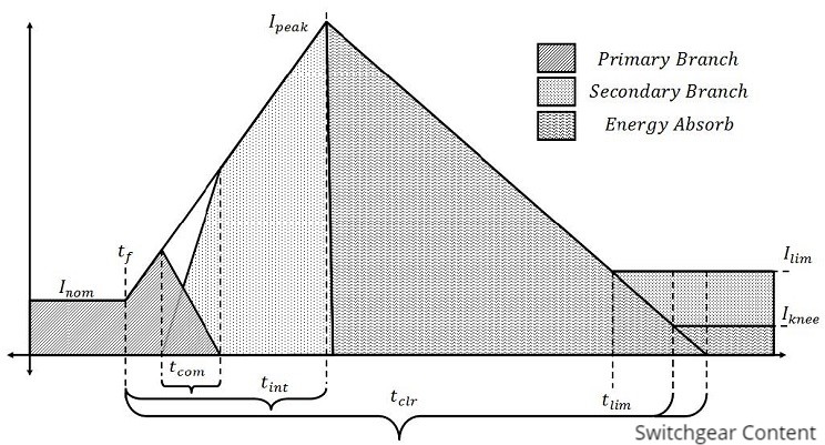
Figure 3 shows a typical fault current waveform with labeled time and current ratings. The dynamics have been exaggerated to allow the definitions to be drawn easily:

- Fault Inception (Tf): The initial moment of fault occurrence.
- Detection Time: Time from Tf to detection of the fault.
- Location Time: Time from detection to determination of which breakers to open.
- Operation Time: Time for the breaker to transition from closed to open.
- Interruption Time (Tint): Time from Tf to sufficient voltage build-up to oppose the fault current.
- Commutation Time (Tcom): Time for current in the primary branch to decay.
- Clearing Time (Tclr): Time from Tf to zero current or Iknee.
- Current Limit Operation Time (Tlim): Time when the breaker starts limiting fault current.
Summary
The Proactive Hybrid Circuit Breaker (PHCB) HVDC, designed by ABB, combines mechanical and semiconductor switches to provide fast, reliable, and efficient fault protection for HVDC systems. The definitions and time frames for hybrid HVDC circuit breakers highlight the unique challenges and requirements of DC protection, emphasizing the need for rapid and precise operation to ensure system safety and stability.
