A Review of Current-Limiting Control of Grid-Forming Inverters Under Symmetrical Disturbances
Grid-forming (GFM) inverters are recognized as a viable solution to increase the penetration of renewable energy in bulk power systems. However, they are physically different from synchronous generators in terms of overcurrent capability. To protect the power semiconductor devices and support the power grid under severe symmetrical disturbances, the GFM control systems should be able to achieve the following requirements: current magnitude limitation, fault current contribution, and fault recovery capability. Various current-limiting control methods are reported in the literature to fulfill these goals, including current limiters, virtual impedance, and voltage limiters. This paper presents an overview of those methods. Emerging challenges that need to be addressed, including temporary overcurrent, unspecified output current vector angle, undesired current saturation, and transient overvoltage, are pointed out.
1.Introduction.
The voltage source behavior of GFM inverters makes their output currents highly dependent on external system conditions. Upon large disturbances such as voltage drops or phase jumps at the point of common coupling (PCC) , synchronous generators can, in general, supply 5–7 p.u. overcurrent [8], while semiconductor-based inverters can only handle 1.2–2 p.u. overcurrent typically , which prevents them from maintaining the voltage profile as in normal operation.The current limiters usually make the inverter behave as a current source during overcurrent conditions, which can facilitate the regulation of the output current vector angle to meet the fault current contribution requirement. In comparison, the virtual impedance methods and voltage limiters can maintain the voltage source behavior of the GFM inverter to some extent during severe disturbances, which may allow for automatic fault recovery. This paper reviews those methods and identifies the emerging challenges that need to be addressed, including temporary overcurrent, unspecified output current vector angle, undesired current saturation, and transient overvoltage.
2. Basics of Current-Limiting Control Methods.
The following figure shows a simplified circuit model of a grid-tied GFM inverter. The GFM inverter consists of an internal voltage source ve and equivalent output impedance. The filter impedance will be included in Ze, if no inner-loop control is utilized. When inner-loop control is used, the filter impedance will not be included in Ze.

3. Current Limiter.
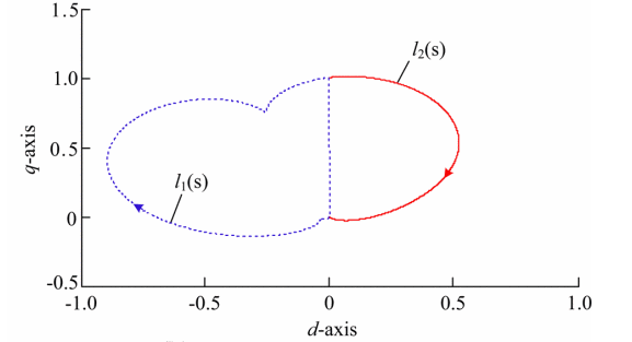
Based on how the saturated current reference i¯ref is calculated, three current limiters are commonly utilized for GFM inverters, including the instantaneous limiter , the magnitude limiter , and the priority-based limiter.The illustration of an instantaneous limiter is shown in Fig.(a), which utilizes an element-wise saturation function to achieve a saturated current reference i¯ref.The illustration of a magnitude limiter is given in Fig. (b), which only decreases the magnitude of the original current reference iref. The angle of i¯ref maintains the same as that of iref.Fig. (c) shows the principle of the priority-based limiter, which not only decreases the magnitude of iref but also prioritizes its angle to a specific value ϕI. Notice that ϕI is a user-defined angle that represents the angle difference between i¯ref and the d-axis oriented to θ.

4. Virtual Impedance.
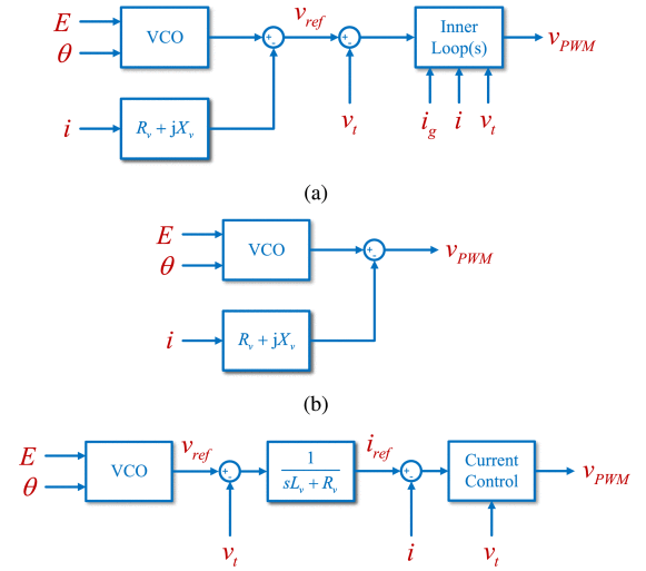
The virtual impedance method that directly modifies the voltage modulation reference and the virtual admittance method with a fast-tracking current control loop can achieve good current limitation performance when severe disturbances occur . In comparison, the virtual impedance method with inner-loop control achieves current limitation based on the hypothesis that the voltage reference vref can be fast tracked by the voltage control loop. Since the bandwidth of the voltage control loop is relatively low , temporary overcurrent may be observed. To deal with this issue, hybrid current-limiting methods that combine the virtual impedance with the priority-based current limiter and the current magnitude limiter are presented.
5. Voltage Limiter.
Voltage limiters aim to directly reduce the voltage difference ∥vPWM−vt∥ to be smaller than ∥Zf∥IM , which modifies the voltage reference generated by the outer-loop control to realize current magnitude limitation . This method is a suggested solution in since it does not require adaptive virtual impedance that can destabilize the system under certain conditions . For the voltage limiters, the inner-control loop is commonly transparent, i.e., vPWM=vref. Subsequently, an equivalent circuit diagram of this current-limiting method can be expressed.

Welcome to our electricity community! Established to facilitate the exchange and cooperation in the electricity industry and bridge professionals, enthusiasts, and related enterprises.
