Excitation Control of Synchronous Machine Using Chopper
Contents
Working Principle of Synchronous Machine Using Chopper
Further Development of Synchronous Machine Using Chopper
Conclusion of Synchronous Machine Using Chopper
Key learnings:
Excitation Control Definition: Excitation control is defined as managing the DC field excitation in a synchronous machine to control its performance.
Working Principle: The working principle of a synchronous machine using a chopper involves stepping up the voltage and controlling it through PWM signals to achieve the desired excitation.
Advantages of Chopper: Using a chopper for excitation control offers high efficiency, compact size, smooth control, and fast response.
Components in Chopper Circuit: Key components include a MOSFET, pulse width modulation signal, rectifier, capacitor, inductor, and protection devices like MOV and fuse.
Future Enhancements: Future developments can include closed-loop control for variable loads and precision components to improve performance and reduce temperature effects.
A synchronous machine is a versatile electric machine used in various fields, such as power generation, maintaining constant speed, and power factor correction. Power factor control is done by managing the DC field excitation. This thesis focuses on how efficiently we can control the field excitation of a synchronous machine.
Conventional DC excitation methods face cooling and maintenance issues due to slip rings, brushes, and commutators, especially as alternator ratings increase. Modern excitation systems aim to reduce these problems by minimizing the number of sliding contacts and brushes.
This trend has led to the development of static excitation using chopper. Modern systems use semiconductor switching devices like diode, thyristors and transistors. In power electronics, a substantial amount of electrical energy is processed, with AC/DC converters being the most typical devices.
The power range typically spans from tens to several hundred watts. In industry, a common application is the variable speed drive used to control the speed of induction motor. Power conversion systems are classified by their input and output power types.
AC to DC (rectifier)
DC to AC (inverter)
DC to AC (DC to DC converter)
AC to AC (AC to AC converter)
It deals with both rotating and static equipment for the generation, transmission, utilization of vast quantities of electrical power. DC-DC converter is electronic circuit which converts a source of direct current from one voltage level to another.
Advantages of power electronic converters are as below-
High efficiency due to low loss in power semiconductor devices.
High reliability of power electronic converter system.
Long life and less maintenance due to absence of moving parts.
Flexibility in operation.
Fast dynamic response compared to electromechani-cal converter system.
There are also some significant disadvantages of power electronic converters like the following-
Circuit in power electronic system have a tendency to generate harmonic in the supply system as well as the load circuit.
AC to DC and DC to AC converter operate at low input power factor under certain operating condition.
Regeneration of power is difficult in power electronic converter system.
In this project, the average voltage across the field of a synchronous machine is controlled using a boost chopper. A boost chopper is a DC to DC converter that provides a higher controlled output voltage from a fixed input DC voltage.
MOSFET is a power electronic semiconductor device which is a fully controlled switch (a switch whose turn on and turn off both can be controlled). MOSFET is used as the switching device in this Boost chopper circuit. The gate terminal of MOSFET is driven by a pulse width modulation (PWM) signal. Which is generated by using a microcontroller. The supply voltage of the chopper has been taken from a diode bridge rectifier by conversion of single phase AC/DC.
This scheme of field excitation control is extremely efficient and compact sized, due to the involvement of power-electronic circuitry. In many industrial applications, such as reactive power control, power factor improvement of transmission line it’s required to change field excitation.
This drive take power from fixed DC source and convert it to variable DC voltage. Chopper systems offer smooth control, high efficiency, faster response and regeneration facility. Basically a Chopper may be considered as DC equivalent of an AC transformer since they behave in an identical manner. As chopper involves one stage conversion, these are more efficient.
Working Principle of Synchronous Machine Using Chopper
To understand details of project plan let’s consider this block diagram below:
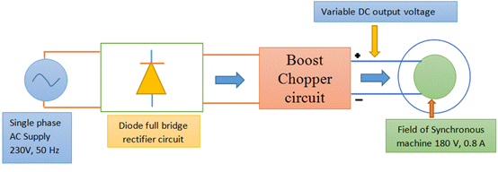
From the above diagram we can say that for 230V input of a full wave rectifier the output voltage is 146 (Approx.) the field voltage of the machine is 180V so we have to step up the voltage though the step up chopper. Now the adjusted DC voltage is fed to the field of the synchronous machine. The output voltage of the chopper can be varied by changing the duty cycle to do so we have to make a pulse generator of adjustable pulse width, and this can be done with help of a Microcontroller.
In microcontroller by comparing a random sequence signal with a constant magnitude we can generate a pulse signal but to avoid loading effect it’s advisable an electrical isolation to do this we are using an Opto coupler. A capacitor has been used in the chopper circuit in order to remove the ripple from the output voltage. It has been simulated that the inductor which has been used in the chopper circuit should be capable of handling 2-3 A of current during the short circuit period. Apart from the desired output voltage, we should also design the circuit so that it can withstand any fault condition.
For overvoltage protection, we will use a metal oxide varistors (MOV) whose resistance depends upon the voltage.
For overcurrent protection, we can use first acting current limiting Fuse.
To improve the quality of the waveform we can use filter circuit basically L or LC filter at the output of the bridge rectifier. The diode which has been should have less reverse recovery time here we can use fast recovery diode.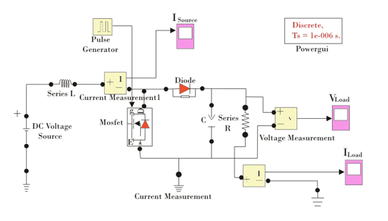
Values of circuit components that have been used
Input DC Voltage = 100V
Pulse voltage = 10V, Duty = 40%
Chopping frequency = 10 KHz
R = 225 ohm (As calculated from the machine rating)
L = 10mH
C = 1pF
Data obtained from the output
Output voltage: 174 V (Average)
Load current: 0.775 A (Average)
Source current: 0.977 A
Further Development of Synchronous Machine Using Chopper
There is still much room for future development that would enhance the system and increase its business value.
Closed loop control
Application areas where the user deals with variable load, needs a closed loop control scheme to maintain constant excitation. Reference voltage and actual output voltage will be compared first and an error signal is generated. This error signal will decide the duty cycle of the chopper.
Reduction in temperature effect
Use of precision capacitor, switching diode can definitely improve the performance, but they will aid to the cost of the project.
Conclusion of Synchronous Machine Using Chopper
In our project, we designed and implemented a low-cost and user-friendly excitation controller using Chopper. The target users of the system are industries requiring smooth, efficient and small controller which gives a wide range of voltage variation. This type of project is really useful in the industrial fields of developing countries like India, where energy crisis is a great concern.
We have learned much through the project. We got the lesson of team work, co-ordination, leadership while going through various phases of development of the project. We were challenged by the complexity of the technologies needed to build the system. This helped us to co-relate and apply the theoretical knowledge we obtained in engineering course.
None of us had experience with electronic control of motor before the project. We needed to learn different concepts and techniques quickly and apply them in the system. The project also provided a chance for us to accumulate experience in pulse signal generation and power MOSFET control area. This project experience has greatly enriched our knowledge and sharpened our technical skills.
Welcome to our electricity community! Established to facilitate the exchange and cooperation in the electricity industry and bridge professionals, enthusiasts, and related enterprises.
