Characteristic of Shunt Wound DC Generator
Shunt Wound DC Generator Definition
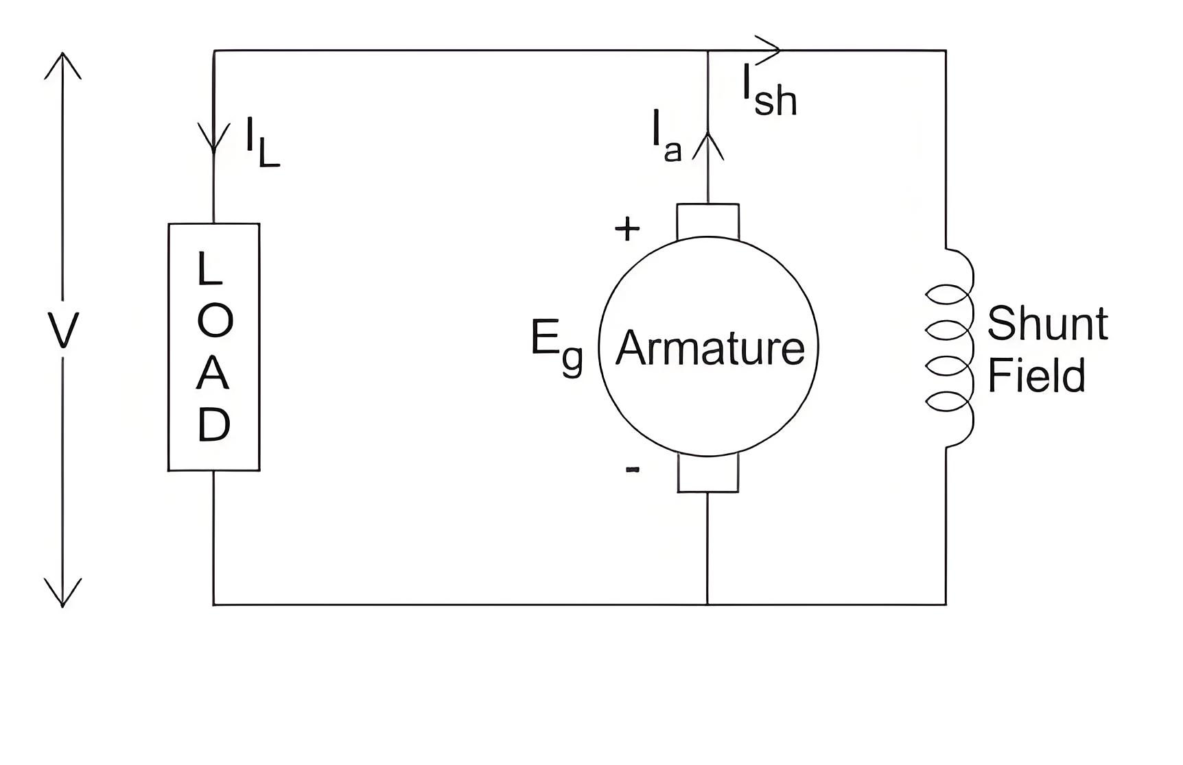
In shunt wound DC generators, the field windings are connected in parallel with the armature conductors. In these types of generators the armature current (Ia) splits into two parts: the shunt field current (Ish) flows through the shunt field winding, and the load current (IL) flows through the external load.

Three most important characteristic of shunt wound DC generators are discussed below:
Magnetic Characteristic
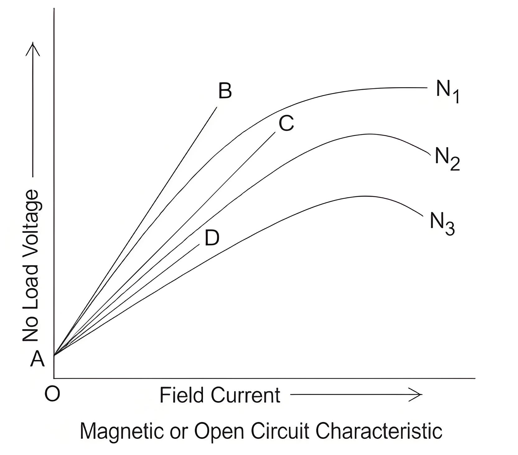
The magnetic characteristic curve shows the relationship between shunt field current (Ish) and no-load voltage (E0). For a given field current, the no-load emf (E0) varies proportionally with the armature’s rotational speed. The diagram illustrates the magnetic characteristic curves for different speeds.
Due to residual magnetism the curves start from a point A slightly up from the origin O. The upper portions of the curves are bend due to saturation. The external load resistance of the machine needs to be maintained greater than its critical value otherwise the machine will not excite or will stop running if it is already in motion. AB, AC and AD are the slops which give critical resistances at speeds N1, N2 and N3. Here, N1 > N2 > N3.
Critical Load Resistance
This is the minimum external load resistance which is required to excite the shunt wound generator.
Internal Characteristic
The internal characteristic curve shows the relationship between generated voltage (Eg) and load current (IL). When the generator is loaded, the generated voltage decreases due to armature reaction, making it lower than the no-load emf. The AD curve represents the no-load voltage, while the AB curve shows the internal characteristic.
External Characteristic
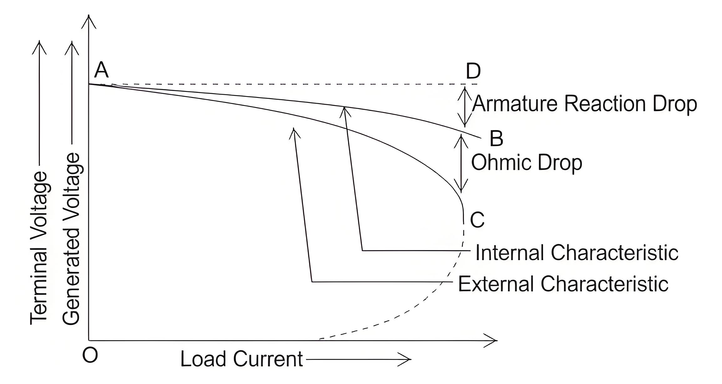
AC curve is showing the external characteristic of the shunt wound DC generators. It is showing the variation of terminal voltage with the load current. Ohmic drop due to armature resistance gives lesser terminal voltage the generated voltage. That is why the curve lies below the internal characteristic curve.
The terminal voltage can always be maintained constant by adjusting the of the load terminal.
When the load resistance of a shunt wound DC generator is decreased, the load current increases, but only up to a certain point (point C). Beyond this, further reduction in load resistance reduces the current. This causes the external characteristic curve to turn back, eventually leading to zero terminal voltage, though some voltage remains due to residual magnetism.
We know, Terminal voltage
Now, when IL

increased, then terminal voltage decreased. After a certain limit, due to heavy load current and increased ohmic drop, the terminal voltage is reduced drastically. This drastic reduction of terminal voltage across the load, results the drop in the load current although at that time load is high or load resistance is low.
That is why the load resistance of the machine must be maintained properly. The point in which the machine gives maximum current output is called breakdown point (point C in the picture).
Welcome to our electricity community! Established to facilitate the exchange and cooperation in the electricity industry and bridge professionals, enthusiasts, and related enterprises.

