What is a Voltage Transformer ?
What is a Voltage Transformer ?
Voltage Transformer Definition
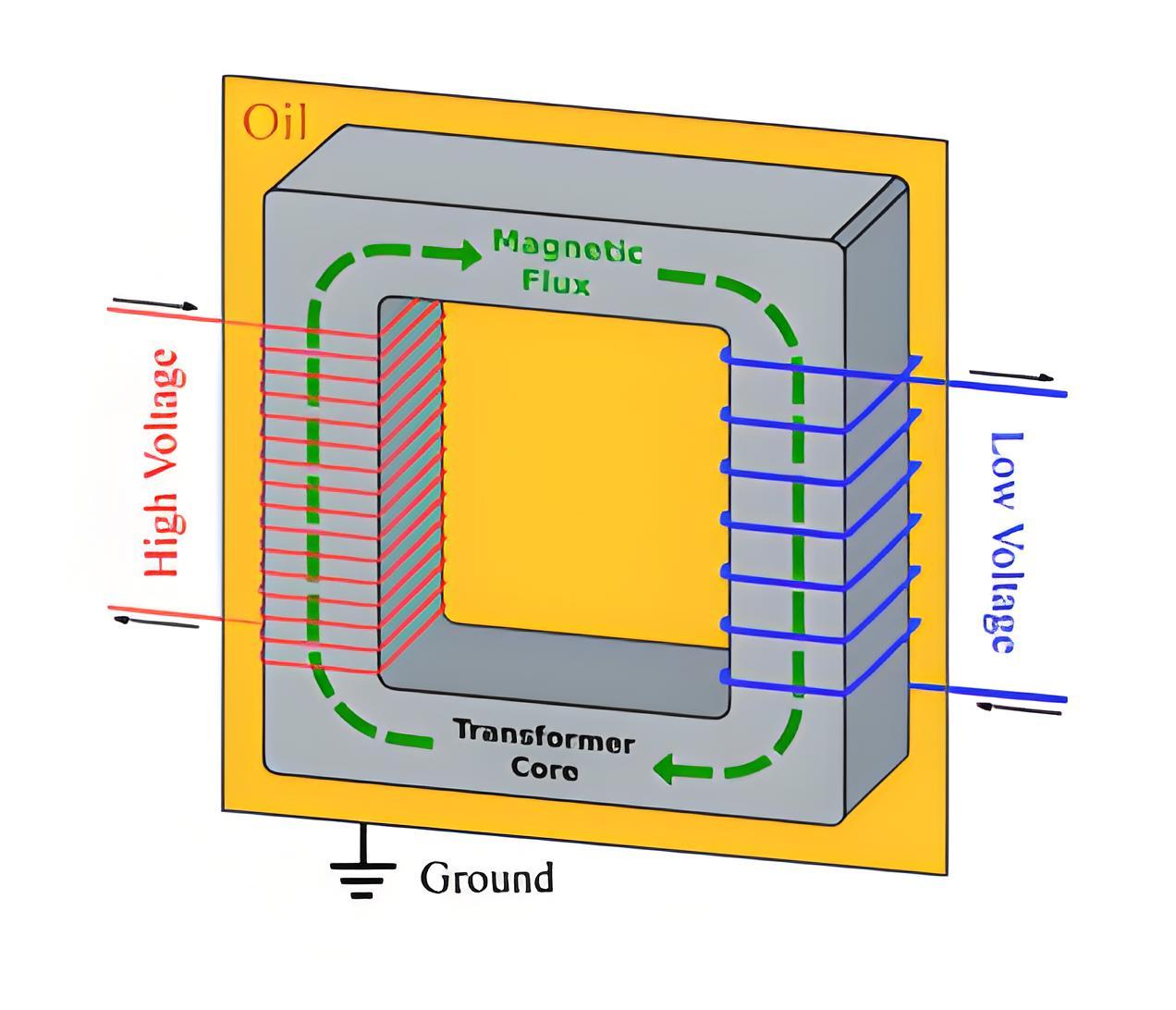
A voltage transformer, also known as a potential transformer, steps down high system voltages to safer, lower levels suitable for standard meters and relays.
Basic Operation
These transformers connect their primary windings across a phase and the ground, operating like other step-down transformers but specifically for voltage management.
Standard Secondary Voltage
The secondary voltage output of a typical voltage transformer is generally 110 V.
Common Errors
Errors in voltage transformers include deviations in voltage ratios and phase alignments, impacting accuracy.
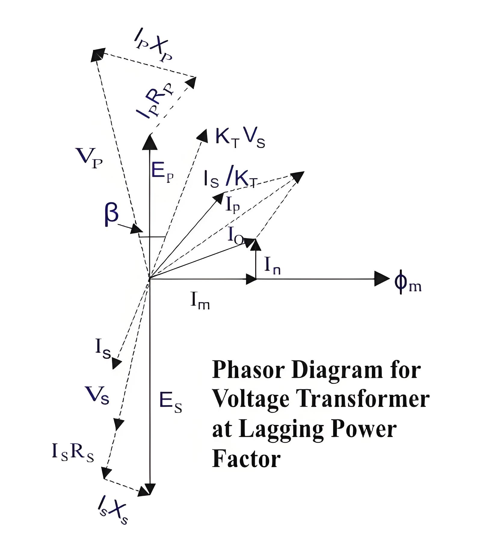
Is – Secondary current.
Es – Secondary induced emf.
Vs – Secondary terminal voltage.
Rs – Secondary winding resistance.
Xs – Secondary winding reactance.
Ip – Primary current.
Ep – Primary induced emf.
Vp – Primary terminal voltage.
Rp – Primary winding resistance.
Xp – Primary winding reactance.
KT – Turns ratio = Numbers of primary turns/number of secondary turns.
I0 – Excitation current.
Im – Magnetizing component of I0.
Iw – Core loss component of I0.
Φm – Main flux.
β – Phase angle error.

Cause of Errors
The voltage applied to the primary of the potential transformer first drops due to the internal impedance of the primary. Then it appears across the primary winding and then transformed proportionally to its turns ratio, to the secondary winding. This transformed voltage across the secondary winding will again drop due to the internal impedance of the secondary, before appearing across burden terminals. This is the reason of errors in potential transformer.
The Electricity Encyclopedia is dedicated to accelerating the dissemination and application of electricity knowledge and adding impetus to the development and innovation of the electricity industry.

