Servo Motor Control: A Complete Guide
Servo Motor Control: A Complete Guide
Key learnings:
Servo Motor Control Defined: Servo motor control allows precise manipulation of motor position, speed, and acceleration through electronic signals.
Feedback Mechanism: The feedback system, often a potentiometer or encoder, ensures the motor’s output matches the control input precisely.
PWM Signal: Pulse-width modulation (PWM) is crucial for setting the servo’s position by varying the duration of electrical pulses.
Arduino and Servo Motors: Using an Arduino board is a popular and effective way to program and control servo motors with minimal hardware setup.
Applications of Servo Motors: Servo motors are essential for projects that require accurate positional control, such as robotics and automated systems.
A servo motor is a motor designed for high precision and accuracy in rotation. It differs from a typical DC motor by its ability to hold a specific position rather than spinning continuously. This feature makes servo motors ideal for robotics, automation, and hobby projects.
This article explains how servo motor control functions, the different types of servo motors, and various control methods and devices. It also provides examples of servo motor applications and projects.
What is a Servo Motor?
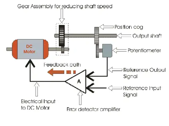
A servo motor is defined as an actuator that allows for precise control of position (angle), speed, and acceleration. A typical servo motor consists of three main components: a DC motor, a control circuit, and a feedback device.
The DC motor powers the servo and connects to gears that reduce speed and increase torque on the output shaft.
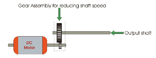
The output shaft is the part of the servo that rotates and moves the load.
The control circuit is responsible for receiving and processing the input signals from an external controller. These signals tell the servo what position, speed, or direction to move to. The control circuit also sends power to the DC motor to drive it.
The feedback device is usually a potentiometer or an encoder that measures the current position of the output shaft.
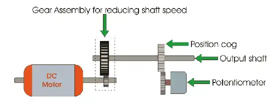
The feedback device relays position data back to the control circuit, which then adjusts the DC motor’s power to align the actual position with the desired position from the input signal.
The feedback loop between the control circuit and the feedback device ensures that the servo can accurately move to and maintain any position within its range of motion.
How to Control a Servo Motor?
Servo motors are controlled by sending a PWM (pulse-width modulation) signal to the signal line of the servo. PWM is a technique that switches a signal on and off rapidly to create pulses of varying widths. The width of the pulses determines the position of the output shaft.
For example, when you send a PWM signal with a pulse width of 1.5 milliseconds (ms), the servo will move to the neutral position (90 degrees).
When you send a PWM signal with a pulse width of 1 ms, the servo will move to the minimum position (0 degrees). When you send a PWM signal with a pulse width of 2 ms, the servo will move to the maximum position (180 degrees).
The PWM signal has a frequency of 50 Hz, which means it repeats every 20 ms. The pulse width can vary from 1 ms to 2 ms within this period.
There are many ways to generate and send PWM signals to servo motors. Some of the most common methods are:
Using an Arduino board or another microcontroller
Using a potentiometer or another analog sensor
Using a joystick or another digital input device
Using a dedicated servo controller or driver
In the following sections, we will explore each of these methods in more detail and see some examples of how they work.
Controlling a Servo Motor with Arduino
Arduino is one of the most popular platforms for controlling servo motors. Arduino boards have built-in PWM outputs that can be used to send signals to servos. Arduino also has a Servo library that makes it easy to write code for servo control.
To control a servo motor with Arduino, you will need:
An Arduino board (such as Arduino UNO)
A standard servo motor (such as SG90)
Jumper wires
A breadboard (optional)
The red wire from the servo connects to 5V on the Arduino board. The black wire from the servo connects to GND on the Arduino board. The white wire from the servo connects to pin 9 on the Arduino board.
To program the Arduino board, you will need to use the Arduino IDE (online or offline). You can use one of the examples from the Servo library or write your own code.
The following code shows how to sweep a servo motor back and forth across 180 degrees using a for loop:
#include <Servo.h> // Include Servo library
Servo myservo; // Create Servo object
int pos = 0; // Variable for position
void setup() {
myservo.attach(9); // Attach Servo object to pin 9
}
void loop() {
for (pos = 0; pos <= 180; pos += 1) { // Loop from 0 to 180 degrees
myservo.write(pos); // Write position to Servo object
delay(15); // Wait 15 ms
}
for (pos = 180; pos >= 0; pos -= 1) { // Loop from 180 to 0 degrees
myservo.write(pos); // Write position to Servo object
delay(15); // Wait 15 ms
}
}
This code uses two loops to increment and decrement the position variable from 0 to 180 degrees and vice versa. It then writes this value to the Servo object using myservo.write(pos). It also adds a delay of 15 ms between each step to slow down the movement.
Upload this code to your Arduino board using the IDE’s Upload button, and watch as your servo motor sweeps back and forth smoothly.
Controlling a Servo Motor with Potentiometer
A potentiometer is an analog sensor that can vary its resistance depending on how much you turn its knob. You can use a potentiometer as an input device for controlling a servo motor.
To control a servo motor with a potentiometer, you will need:
An Arduino board (such as Arduino UNO)
A standard servo motor (such as SG90)
A potentiometer (10k Ohms)
Jumper wires
A breadboard
The wiring diagram for connecting a potentiometer and a servo motor to an Arduino board is shown below:
The red wire from the potentiometer connects to 5V on the Arduino board. The black wire from the potentiometer connects to GND on the Arduino board. The green wire from the potentiometer connects to pin A0 on the Arduino board.
The red wire from the servo connects to 5V on another row on the breadboard. The black wire from the servo connects GND on another row on the breadboard. The white wire from the servo connects pin D9 on another row on the breadboard.
To program your Arduino board, you will need to use the same code as the previous example but change a few lines:
#include <Servo.h> // Include Servo library
Servo myservo; // Create Servo object
int potpin = A0; // Pin connected to potentiometer
int val = 0; // Variable for reading potentiometer value
void setup() {
myservo.attach(9); // Attach Servo object pin D9
}
void loop() {
val = analogRead(potpin); // Read value from potentiometer (0 -1023)
val = map(val,0,1023,0,180); // Map value range (0 -180)
myservo.write(val); // Write mapped value Servo object
delay(15); // Wait 15 ms
}
This code uses the analogRead(potpin) function to read the value from the potentiometer connected pin A0 . It then uses the map(val,0,1023,0,180) function map value range from 0 -1023 degrees. It then writes the mapped value Servo object using myservo.write(val) function . It also adds delay, the same previous example.
You can upload this code to your Arduino board using the Upload button IDE. You should see your servo motor moving according to the knob position potentiometer .
Controlling a Servo Motor with Joystick
A joystick is a digital input device that can detect the direction and magnitude of movement along two axes. You can use a joystick to control a servo motor by mapping the x-axis of the joystick to the angle of the servo.
To control a servo motor with a joystick, you will need the following:
An Arduino board (such as Arduino UNO)
A standard servo motor (such as SG90)
A joystick module (such as KY-023)
Jumper wires
A breadboard
The wiring diagram for connecting a joystick module and a servo motor to an Arduino board is shown below:
!https://www.makerguides.com/wp-content/uploads/2019/01/Servo-motor-control-with-Arduino-and-joystick-wiring-diagram.png
The red wire from the joystick module connects to 5V on the Arduino board. The black wire from the joystick module connects to GND on the Arduino board. The green wire from the joystick module connects to pin A0 on the Arduino board.
The red wire from the servo connects to 5V on another row on the breadboard. The black wire from the servo connects GND on another row on the breadboard. The white wire from the servo connects to pin D9 on another row on the breadboard.
To program your Arduino board, you will need to use the same code as the previous example but change a few lines:
#include <Servo.h> // Include Servo library
Servo myservo; // Create Servo object
int joyX = A0; // Pin connected to joystick x-axis
int val = 0; // Variable for reading joystick value
void setup() {
myservo.attach(9); // Attach Servo object to pin 9
}
void loop() {
val = analogRead(joyX); // Read value from joystick x-axis (0 - 1023)
val = map(val, 0, 1023, 0, 180); // Map value range (0 - 180)
myservo.write(val); // Write mapped value to Servo object
delay(15); // Wait 15 ms
}
This code uses the analog. Read(joyX) function to read the value from the joystick x-axis connected to pin A0. It then uses the map(val, 0, 1023, 0, 180) function to map the value range from 0 – 1023 to 0 – 180 degrees. It then writes this value to the Servo object using myservo.write(val) function. It also adds a delay of 15 ms between each step.
You can upload this code to your Arduino board using the Upload button in the IDE. You should see your servo motor moving according to the position of the joystick.
Controlling a Servo Motor with Servo Controller
A servo controller is a dedicated device that can generate and send PWM signals to multiple servo motors. Servo controllers are useful for projects that require precise and complex control of many servos, such as robotic arms or hexapods.
To control a servo motor with a servo controller, you will need the following:
A servo controller (such as Pololu Maestro)
A standard servo motor (such as SG90)
A USB cable
A power supply
The red wire from the servo connects to VSRV on the servo controller. The black wire from the servo connects GND to the servo controller. The white wire from the servo connects one of the signal pins on the servo controller.
To program your servo controller, you will need to use the Maestro Control Center software.
The following steps show how to control a servo motor with Maestro Control Center:
Connect your servo controller to your computer using a USB cable.
Launch Maestro Control Center and select your device from the list.
Go to the Status tab and move the slider corresponding signal pin connected to your servo.
You should see your servo motor moving according to to angle set slider.
Servo Motor Applications and Projects
Servo motors are versatile and powerful devices that can be used for many applications and projects. Here are some examples of what you can do with servos:
Build a pan/tilt camera mount that can rotate and tilt a camera using two servos.
Build a robotic arm that can move and manipulate objects using multiple servos.
Build a hexapod robot that can walk and turn using many servos.
Build a robotic car that can steer and drive using two servos.
Build an animatronic puppet that can move its eyes, mouth, and head using servos.
Conclusion
In this article, you learned how servo motor control works, what are the different types of servo motors, and how to control them using various methods and devices. You also saw some examples of servo motor applications and projects.
Servo motors are great for adding motion and interactivity to your projects. They are easy to use and control with Arduino or other microcontrollers. They are also widely available and affordable.
Welcome to our electricity community! Established to facilitate the exchange and cooperation in the electricity industry and bridge professionals, enthusiasts, and related enterprises.

