Common-mode Electromagnetic Interference Mitigation for Solid-state Transformers
This article addresses this gap by presenting a comprehensive review of common dc-link MLCs, covering their topological evolution, features, topologies comparison, modulation techniques, control strategies, and industrial application areas. Additionally, future perspectives and recommendations are discussed to provide researchers and engineers with a better understanding of the potential applications and advantages of these converters.
1.Introduction.
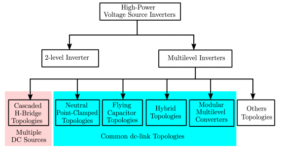
Considering the major evolutionary stages of MLCs, the existing MLC topologies can be categorized into some families,as shown in the following figure.The first family includes CHB-based topologies and has been. These converters feature high modularity and an optimal number of power switches for output levels [31]. However, multiple isolated DC sources are required, necessitating the use of bulky isolation transformers or limiting their employability to applications that have several isolated DC sources. In addition, uneven power sharing between the cascaded power cells is one of the common challenges in this family. The second family includes NPC-based topologies such as 3L-NPC and 3L-T2C converters. These converters are characterized by robust power circuits and straightforward protection. However, dc-link balancing is an essential requirement in the control design of these topologies. FC-based topologies use capacitors as clamping components to increase the number of levels, forming an MLC family characterized by high flexibility, high redundancies and fault-tolerant operation. Hybrid MLCs are formed by basic cells of the conventional topologies and, therefore, combine several advantages of classical MLCs with the capability to produce a high number of levels. MMC topologies constitute an MLCs family that represents a breakthrough for HV applications due to its high efficiency and high modularity.
2. Common Dc-Link Topologies.
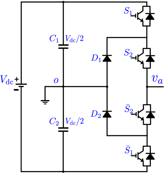
The three-level Active NPC (ANPC) structure has been able to address the issue of power loss sharing through the use of two different modulation techniques called modulation patterns I and II. In which the two clamping diodes are replaced with two active switches to control the current flow direction in zero states. Modulation pattern I cause most of the switching loss to occur in the outer switches of each leg, while pattern II moves the switching losses to the inner switches.Fc category includes the topologies that employ FCs without a clamped neutral point and, accordingly, do not bring the issue of dc-link balancing. In these topologies, FCs are used to replace the dc-sources while generating voltage levels. In general, thanks to the modularity, this family has the capability to generate relatively higher levels compared to the NPC family. Moreover, flexibility, fault-tolerant operation, and improved loss sharing between switches are prominent features of these topologies.Hybrid multilevel converters (HMLCs) combine multiple fundamental topologies to make use of their respective advantages, while overcoming some of their limitations. Predominantly, hybrid topologies can improve the voltage balancing capabilities for both dc-link and FCs and the power loss distribution across switches, while reducing the number of required active and passive components when compared to NPC and FC topologies .
3. Modulation and Control.
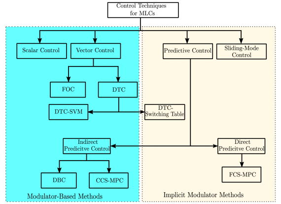
A classification of the major control techniques for multilevel converters is show in the picture below. As with the two-level converter, the cascaded control structure usually consists of outer and inner control stages in addition to the modulator block. Although the inner and outer loops are similar in the two-level and multilevel converters, the modulator stage, which is mainly required for scalar and field-oriented control (FOC) techniques, needs to be adapted as the number of levels goes higher. In this section, first, a review of the most popular, as well as advanced modulators, is presented. Also, the control techniques that do not require a separate modulator will be investigated in more detail.
4. Industrial Applications.
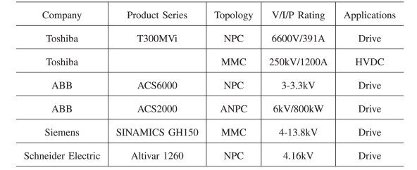
Historically, CHB inverters are characterized by their modularity, fault tolerance, and ability to generate a high number of voltage levels by cascading cells. However, the requirement of multiple isolated DC sources (rectifier+transformer from the industry point of view) limits their applicability for a vast range of power ratings. Indeed, CHB inverters are mostly employed in high-power applications (ranging from hundreds of kilowatts to megawatts) where there are no available components for such ratings. On the other side, common dc-link topologies are characterized by the employment of a single DC source making them a good alternative in various applications such as 3-phase industrial systems. Indeed, they can be employed in many configurations such as 3-Leg 3-Wire, 3-Leg 4-Wire, and 4-Leg 4-Wire in motor drives, PV inverters, fast DC chargers, etc.
Source: IEEE Xplore
Statement: Respect the original, good articles worth sharing, if there is infringement please contact delete.
Welcome to our electricity community! Established to facilitate the exchange and cooperation in the electricity industry and bridge professionals, enthusiasts, and related enterprises.
